What Are Chatter Marks and Why Are They Problematic?
Chatter marks are wave-like patterns on the component surface caused by self-excited vibrations during CNC machining. They are not just a cosmetic issue — chatter marks can significantly impair the functionality, service life and dimensional accuracy of a component.
In practice, vibrations are the most common reason for rework and scrap in CNC manufacturing. A systematic understanding of causes and countermeasures saves time, money and material.
How Do Vibrations Occur in CNC Machining?
The Principle of Regenerative Chatter
The most common form of chatter is regenerative vibration: the tool leaves a waviness on the surface during one revolution. On the next revolution, the cutting edge encounters this wavy surface, which leads to fluctuating chip thickness and thus fluctuating cutting forces. These force fluctuations amplify the vibration — a self-reinforcing cycle develops.
Other Vibration Sources
- Forced vibrations: Caused by tool imbalances, spindle bearing wear or external disturbances
- Chatter on freeform surfaces: Changing engagement conditions with 3D contours
- Workpiece resonances: Thin-walled components vibrate at their natural frequency
The Most Common Causes in Detail
1. Tool Overhang Too Long
The longer the tool protrudes from the tool holder, the lower the dynamic stiffness. Rule of thumb: overhang should be a maximum of 4 times the tool diameter. At L/D > 5, chatter risk increases sharply.
2. Inadequate Workpiece Clamping
A poorly clamped workpiece can move or vibrate under cutting forces. Particularly critical with thin-walled parts and long, slender workpieces. The clamping must be chosen to optimally support the dominant cutting forces.
3. Incorrect Cutting Parameters
The combination of speed, feed rate and depth of cut largely determines whether chatter occurs. The more conservative choice is not always the better one — sometimes a higher speed helps to reach a stable zone.
4. Tool Wear
Worn tools and coatings increase cutting forces and thus vibration risk. Regular tool changes are also important from a vibration perspective.
Systematic Countermeasures
Optimising Cutting Parameters
The simplest measure is adjusting cutting parameters:
- Change speed: Often a 10–15% change is sufficient to find stable zones
- Reduce depth of cut: Lower radial or axial engagement reduces cutting forces
- Increase feed per tooth: Counter-intuitive, but a higher feed can stabilise chip thickness
Improving Tool and Clamping Setup
- Use the shortest possible tool overhang
- High-precision tool holders (shrink-fit or hydraulic chucks) for lower runout
- Strengthen workpiece clamping or use steady rests
- For long tools: use vibration-damped boring bars
Stability Lobe Diagrams
Advanced users employ stability lobe diagrams that visualise the stable and unstable speed-depth combinations. These diagrams show that significantly higher depths of cut are possible at certain speeds — so-called "sweet spots". The result: higher productivity with better surface quality.
Effects on Surface Quality
Vibrations affect the surface on multiple levels:
- Roughness (Ra/Rz): Chatter marks can worsen roughness values by a factor of 5–10
- Waviness: Low-frequency vibrations create wavy surfaces
- Visual appearance: Visible patterns particularly noticeable on high-gloss parts
- Functionality: On sealing surfaces or bearing seats, chatter marks are functionally critical
The right coolant strategy can also contribute to vibration damping.
Frequently Asked Questions (FAQ)
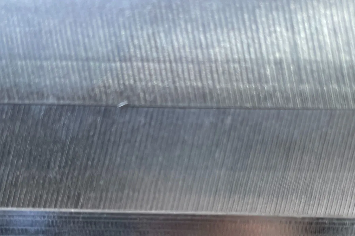
How do I recognise chatter marks on my component?
Chatter marks appear as regular, wave-like patterns on the surface. They are often detectable by touch and clearly visible under certain lighting. A typical sign during machining is a high-frequency, shrill noise.
Can chatter marks be removed afterwards?
Slight chatter marks can be removed by re-finishing with fine cuts, grinding or polishing. For deep chatter marks, re-machining with optimised parameters is often more economical.
Do special milling cutters help against chatter?
Yes — cutters with unequal pitch (variable tooth spacing) disrupt the regenerative effect and significantly reduce chatter risk. Cutters with different helix angles are also an effective measure.
Conclusion: Vibration-Free Machining Is Achievable
Chatter marks are not an unavoidable problem — with the right process understanding, optimised parameters and suitable tools, perfect surface quality can be achieved.
Problems with surface quality? Talk to us — we advise you on optimal machining strategies for your component.